QA011 ESP32 CAM V1.0
1.Introduction
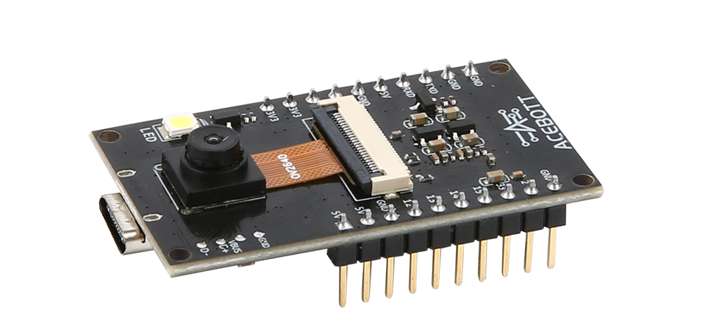
ACEBOTT-ESP32-CAM-V1.0 is the most competitive small size camera module in the industry, which can work independently as the smallest system.
ACEBOTT-ESP32-CAM-V1.0 can be widely used in various Internet of things applications, suitable for home smart devices, industrial wireless control, wireless monitoring, QR wireless identification, wireless positioning system signals and other Internet of things applications.
ACEBOTT-ESP32-CAM-V1.0 adopts DIP package, which can be used directly when it is inserted into the bottom plate to realize the rapid production of products, provide customers with highly reliable connection, and facilitate the application in various Internet of Things hardware terminal occasions.
2.Features
Ultra-small volume 802.11b/g/n Wi-Fi SoC module
The low-power dual-core 32-bit CPU can be used as an application processor
The main frequency up to 240 MHz, computing power up to 600 DMIPS
Built-in 520 KB SRAM, external 8MB PSRAM
Support for UART / SPI / I2C / PWM / ADC / DAC interfaces
Support for OV2640 and OV7670 cameras, with a built-in flash
Support image WiFI upload
Supports multiple dormancy modes
Lwip and FreeRTOS
Supports the STA / AP / STA + AP working mode
Support Smart Config / AirKiss one-click distribution network
3.Specifications
Parameters |
Value/Description |
|---|---|
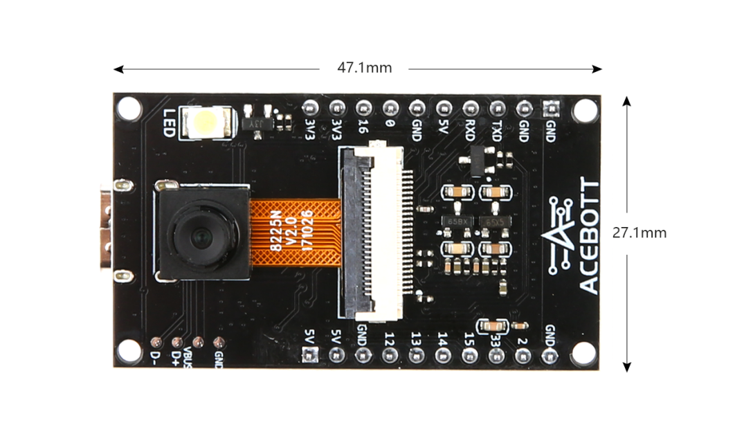
Size |
27.1x47.1(mm) |
Encapsulation |
DIP-20 |
Power supply |
Type-c |
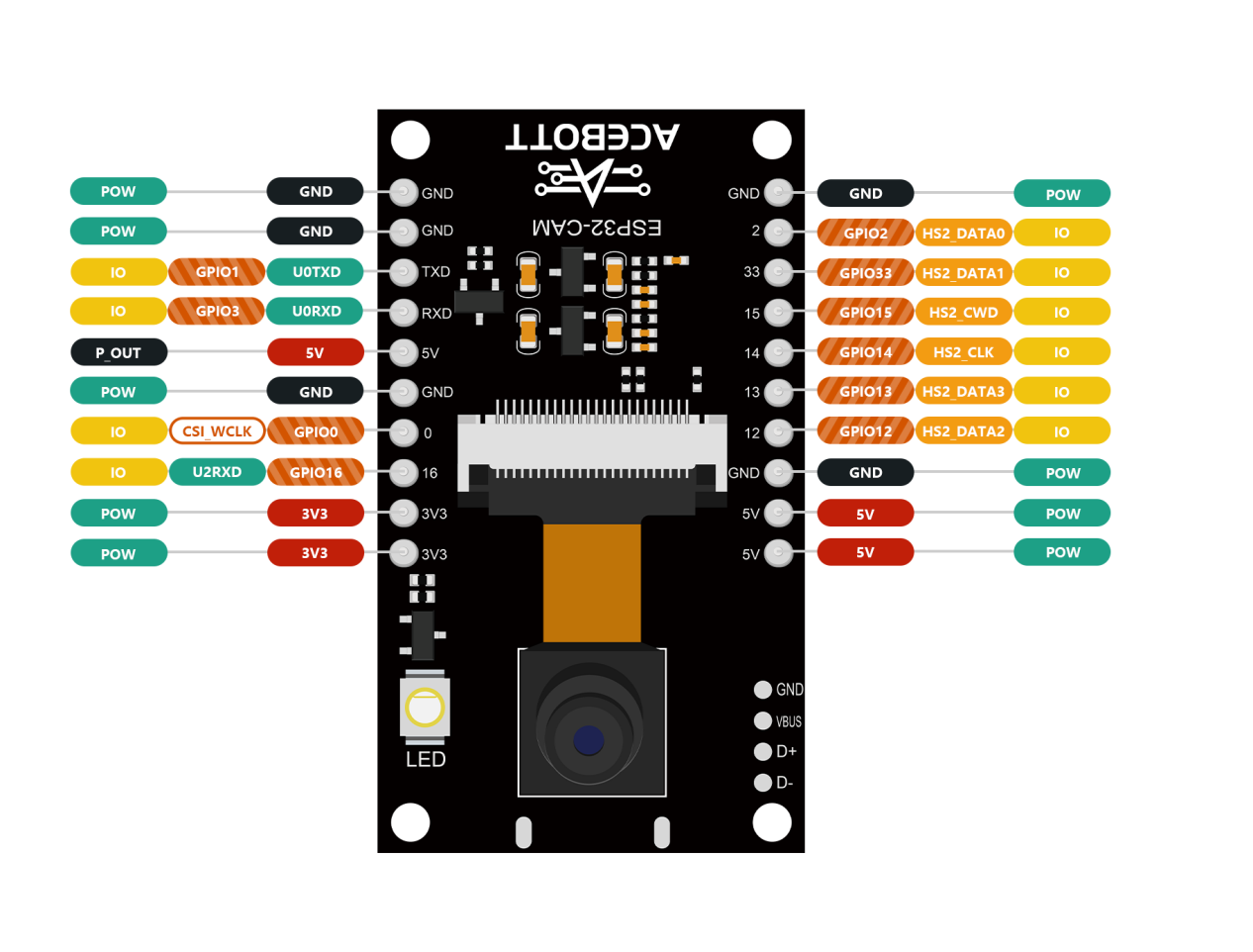
Support interface |
UART/SPI/I2C/PWM |
Number of IO ports |
10 |
Serial port baud rate |
Support 110 ~ 4608000 bps, Default 115200 bps |
SPI Flash |
Default 32Mbit |
Image output format |
JPEG (supported by OV2640 only), BMP, GRAYSCALE |
Spectrum range |
2400~2483.5MHz |
Antenna form |
External PCB antenna, gain 2 dBi |
Power consumption |
Turn off the flash:180mA@5V |
Turn on the flash light and adjust the brightness to the maximum:310mA@5V |
|
Deep-sleep: The lowest power consumption can reach 6 mA@5V |
|
Moderm-sleep: The minimum level is 20 mA@5V |
|
Light-sleep: The minimum value can reach 6.7 mA@5V |
|
Security |
WEP/WPA-PSK/WPA2-PSK |
Power supply range |
4.75-5.25V |
Operating temperature |
-20 °C ~ 70 °C |
Storage environment |
-40 °C ~ 1250 °C,<90%RH |
4.Sample Code
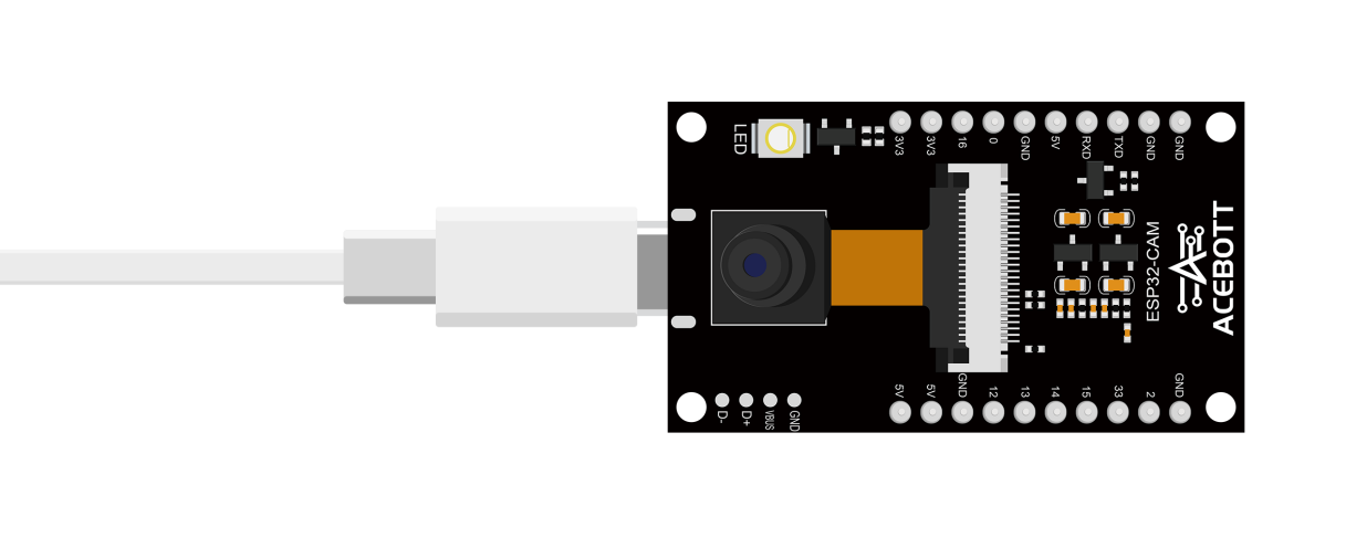
Connect the board to the computer using a Type-C data cable: Select “ESP32” -> “ESP32 Dev Module” from the Tools > Board menu. Choose the appropriate Port. And upload it to the board using the Upload button.
(1)Wiring Diagram
(2)Sample Code
1#include "esp_camera.h"
2#include <WiFi.h>
3#include "esp_timer.h"
4#include "img_converters.h"
5#include "Arduino.h"
6#include "fb_gfx.h"
7#include "soc/soc.h" //disable brownout problems
8#include "soc/rtc_cntl_reg.h" //disable brownout problems
9#include "esp_http_server.h"
10
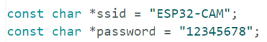
11const char *ssid = "ESP32-CAM";
12const char *password = "12345678";
13WiFiServer server(100);
14WiFiClient client;
15
16#define PART_BOUNDARY "123456789000000000000987654321"
17// #define CAMERA_MODEL_AI_THINKER
18#define PWDN_GPIO_NUM 32
19#define RESET_GPIO_NUM -1
20#define XCLK_GPIO_NUM 0
21#define SIOD_GPIO_NUM 26
22#define SIOC_GPIO_NUM 27
23#define Y9_GPIO_NUM 35
24#define Y8_GPIO_NUM 34
25#define Y7_GPIO_NUM 39
26#define Y6_GPIO_NUM 36
27#define Y5_GPIO_NUM 21
28#define Y4_GPIO_NUM 19
29#define Y3_GPIO_NUM 18
30#define Y2_GPIO_NUM 5
31#define VSYNC_GPIO_NUM 25
32#define HREF_GPIO_NUM 23
33#define PCLK_GPIO_NUM 22
34
35#define RXD2 14
36#define TXD2 13
37
38static const char* _STREAM_CONTENT_TYPE = "multipart/x-mixed-replace;boundary=" PART_BOUNDARY;
39static const char* _STREAM_BOUNDARY = "\r\n--" PART_BOUNDARY "\r\n";
40static const char* _STREAM_PART = "Content-Type: image/jpeg\r\nContent-Length: %u\r\n\r\n";
41httpd_handle_t stream_httpd = NULL;
42
43static esp_err_t stream_handler(httpd_req_t *req){
44 camera_fb_t * fb = NULL;
45 esp_err_t res = ESP_OK;
46 size_t _jpg_buf_len = 0;
47 uint8_t * _jpg_buf = NULL;
48 char * part_buf[64];
49 res = httpd_resp_set_type(req, _STREAM_CONTENT_TYPE);
50 if(res != ESP_OK){
51 return res;
52 }
53while(true){
54 fb = esp_camera_fb_get();
55 if (!fb) {
56 Serial.println("Camera capture failed");
57 res = ESP_FAIL;
58 } else {
59 if(fb->width > 400){
60 if(fb->format != PIXFORMAT_JPEG){
61 bool jpeg_converted = frame2jpg(fb, 80, &_jpg_buf, &_jpg_buf_len);
62 esp_camera_fb_return(fb);
63 fb = NULL;
64 if(!jpeg_converted){
65 Serial.println("JPEG compression failed");
66 res = ESP_FAIL;
67 }
68 } else {
69 _jpg_buf_len = fb->len;
70 _jpg_buf = fb->buf;
71 }
72 }
73}
74if(res == ESP_OK){
75 size_t hlen = snprintf((char *)part_buf, 64, _STREAM_PART, _jpg_buf_len);
76 res = httpd_resp_send_chunk(req, (const char *)part_buf, hlen);
77 }
78if(res == ESP_OK){
79 res = httpd_resp_send_chunk(req, (const char *)_jpg_buf, _jpg_buf_len);
80 }
81if(res == ESP_OK){
82 res = httpd_resp_send_chunk(req, _STREAM_BOUNDARY, strlen(_STREAM_BOUNDARY));
83 }
84
85if(fb){
86 esp_camera_fb_return(fb);
87 fb = NULL;
88 _jpg_buf = NULL;
89 } else if(_jpg_buf){
90 free(_jpg_buf);
91 _jpg_buf = NULL;
92 }
93 if(res != ESP_OK){
94 break;
95 }
96 //Serial.printf("MJPG: %uB\n",(uint32_t)(_jpg_buf_len));
97 }
98 return res;
99}
100void startCameraServer(){
101 httpd_config_t config = HTTPD_DEFAULT_CONFIG();
102 config.server_port = 80;
103 httpd_uri_t index_uri = {
104 .uri = "/",
105 .method = HTTP_GET,
106 .handler = stream_handler,
107 .user_ctx = NULL
108 };
109if (httpd_start(&stream_httpd, &config) == ESP_OK) {
110 httpd_register_uri_handler(stream_httpd, &index_uri);
111 }
112}
113
114void setup() {
115 // WRITE_PERI_REG(RTC_CNTL_BROWN_OUT_REG, 0); //disable brownout detector
116 Serial.begin(115200);
117 Serial2.begin(115200, SERIAL_8N1, RXD2, TXD2);
118
119 // Serial.setDebugOutput(false);
120
121 camera_config_t config;
122 config.ledc_channel = LEDC_CHANNEL_0;
123 config.ledc_timer = LEDC_TIMER_0;
124 config.pin_d0 = Y2_GPIO_NUM;
125 config.pin_d1 = Y3_GPIO_NUM;
126 config.pin_d2 = Y4_GPIO_NUM;
127 config.pin_d3 = Y5_GPIO_NUM;
128 config.pin_d4 = Y6_GPIO_NUM;
129 config.pin_d5 = Y7_GPIO_NUM;
130 config.pin_d6 = Y8_GPIO_NUM;
131 config.pin_d7 = Y9_GPIO_NUM;
132 config.pin_xclk = XCLK_GPIO_NUM;
133 config.pin_pclk = PCLK_GPIO_NUM;
134 config.pin_vsync = VSYNC_GPIO_NUM;
135 config.pin_href = HREF_GPIO_NUM;
136 config.pin_sccb_sda = SIOD_GPIO_NUM;
137 config.pin_sccb_scl = SIOC_GPIO_NUM;
138 config.pin_pwdn = PWDN_GPIO_NUM;
139 config.pin_reset = RESET_GPIO_NUM;
140 config.xclk_freq_hz = 20000000;
141 config.frame_size = FRAMESIZE_UXGA;
142 config.pixel_format = PIXFORMAT_JPEG; // for streaming
143 //config.pixel_format = PIXFORMAT_RGB565; // for face detection/recognition
144 config.grab_mode = CAMERA_GRAB_WHEN_EMPTY;
145 config.fb_location = CAMERA_FB_IN_PSRAM;
146 config.jpeg_quality = 12;
147 config.fb_count = 1;
148
149 // if PSRAM IC present, init with UXGA resolution and higher JPEG quality
150 // for larger pre-allocated frame buffer.
151 if(config.pixel_format == PIXFORMAT_JPEG){
152 if(psramFound()){
153 config.jpeg_quality = 10;
154 config.fb_count = 2;
155 config.grab_mode = CAMERA_GRAB_LATEST;
156 } else {
157 // Limit the frame size when PSRAM is not available
158 config.frame_size = FRAMESIZE_SVGA;
159 config.fb_location = CAMERA_FB_IN_DRAM;
160 }
161 } else {
162 // Best option for face detection/recognition
163 config.frame_size = FRAMESIZE_240X240;
164#if CONFIG_IDF_TARGET_ESP32S3
165 config.fb_count = 2;
166#endif
167 }
168 // camera init
169 esp_err_t err = esp_camera_init(&config);
170 if (err != ESP_OK)
171 {
172 Serial.printf("Camera init failed with error 0x%x", err);
173 return;
174 }
175 sensor_t *s = esp_camera_sensor_get();
176 //drop down frame size for higher initial frame rate
177 //s->set_framesize(s, FRAMESIZE_SXGA); //Byte length sampling value:60000 #9 (High picture quality) 1280x1024
178 s->set_framesize(s, FRAMESIZE_SVGA); //Byte length sampling value:40000 #7 (Medium picture quality) 800x600
179 //s->set_framesize(s, FRAMESIZE_QVGA); //Byte length sampling value:10000 #4 (Poor picture quality) 320x240
180
181 s->set_vflip(s, 1); //Image orientation Settings (up and down)
182 s->set_hmirror(s, 1); //Image orientation Settings (left and right)
183
184 WiFi.setTxPower(WIFI_POWER_19_5dBm);
185 WiFi.mode(WIFI_AP);
186 WiFi.softAP(ssid, password, 5);
187 // WiFi.softAP(ssid, password);
188 Serial.print("\r\n");
189 startCameraServer();
190 Serial.print("\r\n");
191 Serial.print("Camera Ready! Use 'http://");
192 Serial.print(WiFi.softAPIP());
193 Serial.println("' to connect");
194
195 server.begin(); // Starting the server
196 delay(100);
197
198}
199void loop() {
200 delay(1);
201
202}
5.Test Result
After uploading the program, the imaging effect will be displayed on the web end. First of all, the terminal device needs to be connected to the WiFi issued by the camera module.
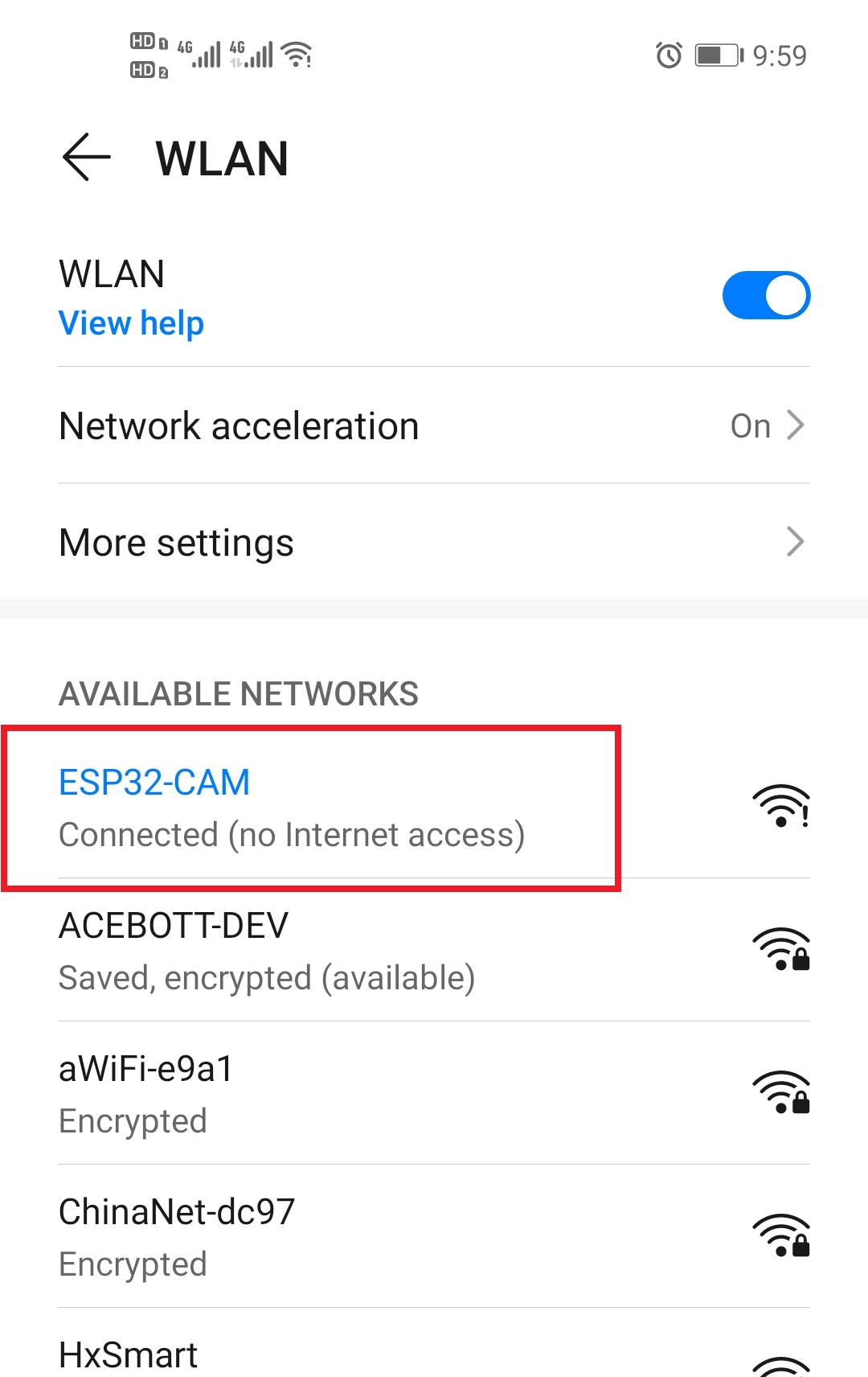
Hint
The WiFi name and password in the program can be customized.
The IP address of the camera module in AP mode is: 192.168.4.1, and then enter the IP address in the address bar of the terminal browser to access the web page of the camera image. By moving the direction of the camera, you can see the live imaging effect of the camera module on the web page.

6.Related Resources